Approved rough opening
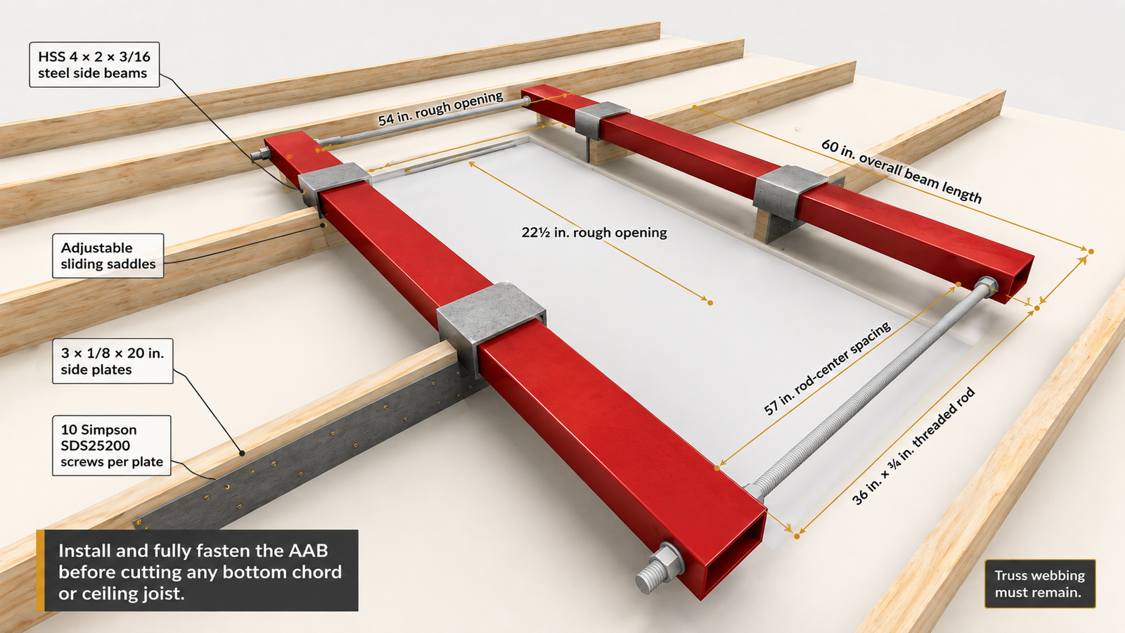
Designed for a 54-inch-long by 22½-inch-wide rough opening.
Attic access solutions
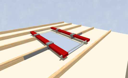
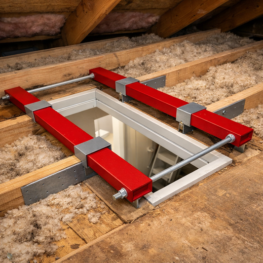
The engineered bulkhead transfers roof-spread tension forces around a 54 × 22½-inch attic rough opening. Confirm roof span, pitch, ground snow load, and framing against the current design report before ordering.
Engineered structural solution
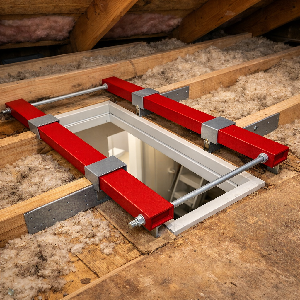
Transfers tension forces around an attic opening using two steel side beams, threaded rods, and adjustable sliding saddles.
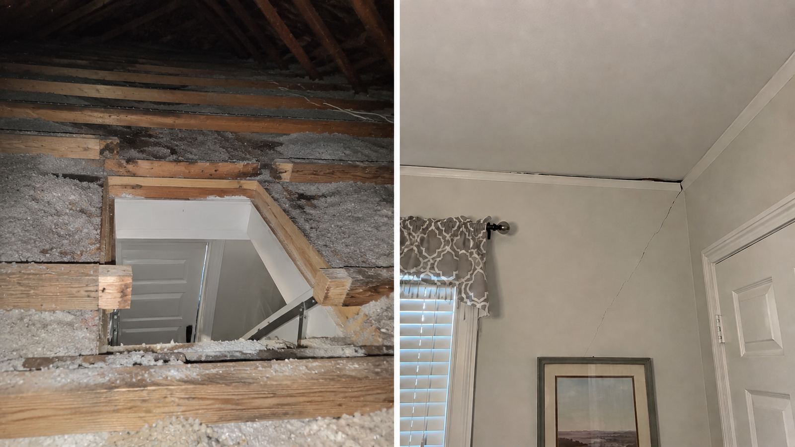
Important Product Documents
Review the available engineering, installation, and selection documents before ordering or beginning work.
Application first
Review the basic application and limits below. The current design report and installation instructions remain the technical source of truth.
Designed for a 54-inch-long by 22½-inch-wide rough opening.
Only a section of the bottom chord may be removed; truss webbing must remain.
The bulkhead must be installed and fully fastened before bottom chords or ceiling joists are cut.
How the system works
Two HSS steel side beams bridge the attic opening. Four adjustable sliding saddle-and-plate connections attach to the truss bottom chords or ceiling joists, while two threaded rods hold the assembly together and transfer tension forces around the opening.
Key technical points
Clear next steps
Record the member size, span or opening, accessible length, and relevant project conditions.
Use the product options and the applicable report, chart, or table.
Follow the complete fastening and installation requirements supplied for the product.
Need help selecting?
Send the project dimensions and a few clear photos. We’ll help identify the right product or tell you when the published solution does not fit.
Contact Nolan Structural Products